AQMWIE01 – Aqua-Meter Ultraschall-Klemme (WLAN)
Produktbeschreibung
Die Wassersensor-Klemme misst mit einem „Time of Flight"-Messverfahren den Durchfluss und die Temperatur in einem Wasserrohr und überträgt die Daten per Funk. Durch eine interne Analyse des Durchflusses werden Wasserleckagen und andere Anomalien erkannt und der Besitzer alarmiert.
Das Gerät wird von außen auf das Wasserrohr geklemmt, ohne dass die Wasserversorgung unterbrochen werden muss. Das flexible Design und die innovative Software ermöglichen die Anwendung auf Wasserrohren zwischen 16 und 50 mm mit vielen aktuell am Markt verfügbaren Materialien wie PEX, PEX AL, weiches plastikummanteltes Weichkupfer oder PE. Alle Anforderungen der Meterrichtlinie (MID) der Europäischen Gemeinschaft werden erfüllt. Mit nur 60 mm Platzbedarf über dem Wasserrohr und einer Länge von 115 mm ist das Gerät sehr flach und kurz und damit einfach zu verbauen.
Das Gerät kann entweder über USB-C oder über zwei AA-Alkaline-Zellen versorgt werden. Immer wenn eine externe Stromquelle vorhanden ist, wird diese unabhängig von den eingelegten Batterien verwendet.
Das System funkt über WLAN und wird über eine App auf dem Mobiltelefon gesteuert. Zusätzlich können Daten an einen MQTT-Server oder einen HTTP-Webhook gesendet werden, um in ein Smart Home-System integriert zu werden.
Messprinzip
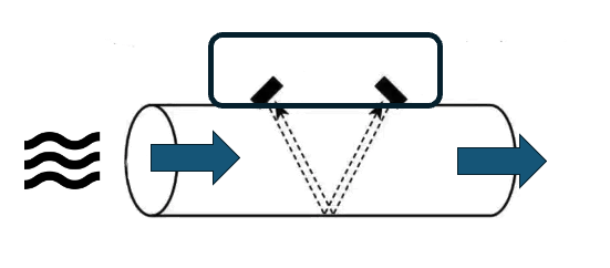
Die Wassersensor-Klemme verwendet Ultraschallwellen und die Methode „differenzielle Laufzeit (DTOF)", um den Wasserfluss zu messen. Bei dieser Methode werden zwei Ultraschallwandler – Transducer genannt – verwendet, um Signale in entgegengesetzte Richtungen durch das Rohr und das Wasser zu senden. Das vom stromaufwärts gelegenen Wandler gesendete Signal bewegt sich entlang der Wasserflussrichtung und wird vom stromabwärts gelegenen Wandler erfasst. Das zweite Signal, das vom stromabwärts gelegenen Wandler gesendet wird, bewegt sich gegen die Wasserflussrichtung, bewegt sich langsamer voran und trifft später auf den stromaufwärts gelegenen Wandler. Die Differenz in der Laufzeit zwischen den beiden Signalen steht direkt im Verhältnis zur Geschwindigkeit des Wassers im Rohr und somit zur Durchflussrate.
Um diese Methode besser zu verstehen, kann man sie sich wie das Schwimmen in der Strömung eines Flusses vorstellen. Indem man flussaufwärts und flussabwärts schwimmt und die Zeit vergleicht, die benötigt wird, um die gleiche Strecke in jeder Richtung zurückzulegen, kann man die Geschwindigkeit des Wasserflusses im Fluss abschätzen.
Das Prüfsignal des Geräts hat eine Frequenz von 1 MHz und ist von sehr geringer Leistung, was es unhörbar und harmlos für Menschen und Tiere macht. Darüber hinaus werden die Schallwellen dieser hohen Frequenz stark durch den atmosphärischen Druck der Luft gedämpft und können in der Praxis nicht über das Rohr hinaus strahlen. Die Wassersensor-Klemme wird daher keine Menschen oder andere Geräte stören.
Aufbau des Sensors
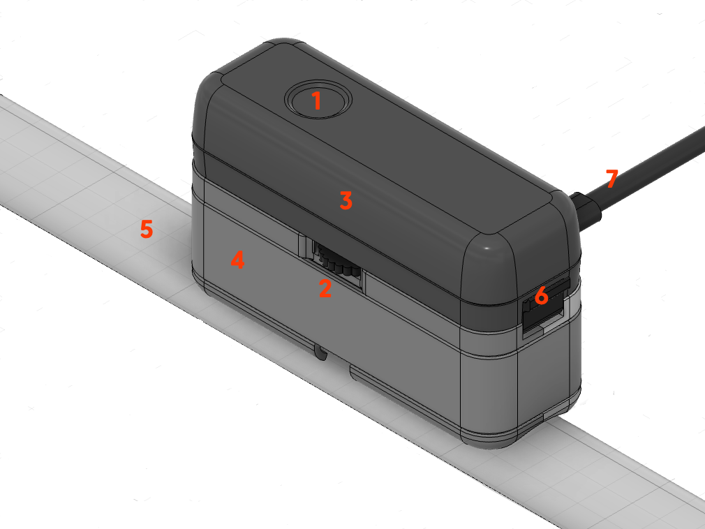
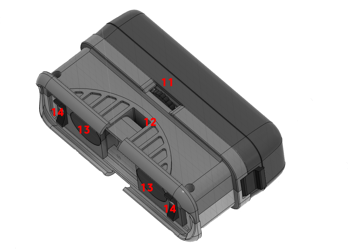
Der Sensor besteht aus zwei Hauptbauteilen:
- Sensor-Basis (4): Wird mit dem Wasserrohr verbunden. Sie enthält den Temperatursensor sowie die zwei Ultraschall-Transducer (13). Deren Abstand zueinander kann mit dem Handrad (2/11) verändert und damit an die vorhandene Rohrstärke (5) und das Material des Wasserrohres angepasst werden.
- Elektronik-Kapsel (3): Enthält Elektronik, Batterien, LED (1), Taste (1) etc. Sie wird auf die Sensor-Basis aufgesetzt und mit einer Klappe (6) fixiert. Alternativ zu Batterien kann der Sensor über ein USB-C Netzteil (7) versorgt werden.
Zur Fixierung der Basis am Rohr werden zwei kleine Zwischen-Adapter (14) benötigt, die genau dem Durchmesser des Wasserrohres entsprechen. Eine Auswahl für die wichtigen Rohrdurchmesser liegt dem Produkt bei. Weiterhin muss der Sensor mittels eines Kabelbinders oder alternativ einer Schlauchschelle fest an das Wasserrohr montiert werden.
Im Betrieb ist die Kapsel fest mit der Basis verbunden. Zu Wartungszwecken oder für einen Batteriewechsel kann sie ohne Gefahr von der Basis getrennt werden. Wird die Kapsel ohne Basis mit Strom betrieben, erfolgt eine entsprechende Alarmmeldung und es ist keine Messung des Wasserverbrauches möglich.
Verbindung und Kommunikation
Die WLAN-Einrichtung erfolgt über die Konfigurationsseite des Gerätes (SSID „Scope"). Eine ausführliche Schritt-für-Schritt-Anleitung finden Sie unter WLAN-Anbindung.
Für erfahrene Anwender
Neben der Aqua-Scope App stehen weitere Kommunikationsoptionen zur Verfügung, die über Konfiguration → Kommunikationsoptionen in der App aktiviert werden:
- MQTT – Integration in MQTT-basierte Systeme
- Home Assistant – Automatische Erkennung im Dashboard
- JSON Webhook – Eigener Webdienst mit HTTP POST
- Modbus IP – Industrielles Protokoll (TCP Port 502)
- Lokaler Webserver – Direkter Zugriff per Browser im LAN
Der lokale Webserver und Modbus IP sind nur im Netzteilbetrieb verfügbar, nicht im Batteriemodus.
Montage
Der Montageort und die richtige Befestigung des Sensors am Rohr haben den entscheidenden Einfluss auf die Genauigkeit der Messung. Ein ungünstiger Montageort oder eine falsche Befestigung des Sensors können im Extremfall dazu führen, dass der Sensor überhaupt keine Messergebnisse liefert.
Geeignete Montagestelle finden
(1) Für eine genaue Messung muss das Wasser frei von Turbulenzen und Luftblasen sein. Daher darf das Gerät nicht in der Nähe von Rohrbögen oder anderen Wasserinstallationen wie Hauptabsperrventilen, Rückflussverhinderern oder dem Druckminderer installiert werden. Es ist sicherzustellen, dass auf jeder Seite der Rohrbögen usw. ein Mindestabstand von 20 cm eingehalten wird und dass der Installationspunkt keine Ansammlung kleiner Luftblasen zulässt, die immer dann auftreten, wenn das Wasser schnell durch das Rohr fließt.
(2) Das Rohr an der Montagestelle muss glatt und rostfrei sein, damit auch auf der Außenseite keine Lufteinschlüsse das Messverfahren stören. Bei Kunststoffrohren reicht ein Reinigen der Oberfläche, bei metallischen Rohren kann es sinnvoll sein, diese mit feinem Sandpapier zu polieren.
(3) Nicht zuletzt muss die Montagestelle per Funk erreichbar sein. Eine stabile Funkverbindung ist am einfachsten zu testen, indem der Sensor noch vor der finalen Montage bereits ins Funknetz eingebunden wird.
- Sauberes rostfreies Rohr
- Mind. 20 cm Abstand zu Winkeln und Armaturen
- Nicht an abfallenden Rohren
- Funknetz-Abdeckung
Sensor für Einbau vorbereiten
Es wird empfohlen, den Sensor am Ort des Einbaus, aber vor der finalen Montage am Wasserrohr, bereits mit dem Funknetz zu verbinden. Dies ist jedoch keine Installationsvoraussetzung.
- Aus dem Satz von Distanzstücken werden die beiden dem Rohrdurchmesser entsprechenden Teile ausgewählt und neben die Transducer in die entsprechenden Schlitze gesteckt.
- Die Transducer an der Sensorbasis sind mittels des kleinen Handrades an der Seite verschiebbar und können so an verschiedene Rohrdurchmesser und Rohrmaterialien angepasst werden. Die Transducer können bis zu 26 mm weit auseinandergeschoben werden. Tabelle 1 gibt den notwendigen Abstand in Millimetern für verschiedene Rohrdurchmesser und -materialien an. Ist das Rohr ummantelt (zum Beispiel PEX mit Aluminiummantel oder Kupfer mit Plastikmantel), dann ist das Grundmaterial aus der Tabelle zu wählen. Der Abstand sollte mit einer Genauigkeit von +/- 2 mm getroffen werden.
| Durchmesser | 20 mm | 26 mm | 33 mm | 42 mm | 56 mm |
|---|---|---|---|---|---|
| Weichkupfer | 0 mm | 0 mm | 5 mm | 13 mm | 20 mm |
| PEX | 0 mm | 0 mm | 5 mm | 20 mm | 20 cm |
| PP | 0 mm | 0 mm | 5 mm | 15 mm | 18 mm |
Tabelle 1: Abstände der Transducer in Abhängigkeit vom verwendeten Wasserrohr
- Die Kontaktpads werden auf die Transducer aufgeklebt. Zuerst wird die weiße Schutzfolie abgezogen und der Klebepad direkt über der Transducerfläche platziert. Der Klebepad sollte dabei mit der Seite des Gehäuses abschließen, die dem jeweils anderen Transducer zugewandt ist. Die roten Schutzfolien auf den Kontaktpads der Transducer werden entfernt. Die Buffer-Pads sind sehr klebrig und werden auch ohne weitere Fixierung den Sensor am Rohr festhalten. Die Pads werden am Anfang nur ganz leicht angedrückt, um sie bei Bedarf nochmals lösen zu können. Falls Sie beim Ablösen einen oder beide Pads zerstören, liegen dem Produkt Ersatzpads bei.
- Unter Beachtung der Fließrichtung (großer Pfeil am Typenschild des Gerätes) wird der Sensor an das Wasserrohr angelegt und mit dem Kabelbinder locker fixiert.
- Abstand der Transducer einstellen
- Kontaktpads nicht zu fest aufdrücken
- Fließrichtung des Wassers beachten
Sensor am Rohr anbringen
Die genaue Positionierung des Sensors auf dem Rohr hat entscheidenden Einfluss auf Funktionsfähigkeit und Genauigkeit des Gerätes. Dabei ist Folgendes zu beachten:
- Der Sensor muss absolut parallel zum Rohr aufgesetzt werden. Die Distanzstücke helfen dabei, genau dieses Ziel zu erreichen.
- Der Sensor sollte seitlich am Rohr angebracht werden. Oben im Rohr können sich Luftblasen sammeln, unten im Rohr können sich Ablagerungen befinden.
- Der Sensor muss einen definierten Abstand zum Rohr haben, der komplett durch die Kontaktpuffer gefüllt wird. Die Distanzstücke helfen ebenfalls dabei, genau dieses Ziel zu erreichen.
- Der Anpressdruck des Sensors muss optimal sein. Das gilt es bei der Montage selbst zu optimieren. Dazu gibt es bei Bedarf eine Positionierhilfe.
Befestigen Sie den Sensor mit dem mitgelieferten Kabelbinder. Der Kabelbinder muss so straff wie möglich zugezogen werden. Danach wird der Sensor mit Strom versorgt. Sobald er sich mit dem Funknetz verbunden hat, wird die LED entweder langsam rot oder langsam grün blinken:
- Langsam grün (alle 5 Sekunden): Gerät ist betriebsbereit.
- Langsam rot: Positionierung muss optimiert werden.
Montieren Sie den Sensor stets seitlich am Rohr, nicht oben oder unten. Dies verbessert die Messgenauigkeit und vermeidet Ablagerungen an den Wandlern.
Positionierhilfe
Der Sensor hat eine eingebaute Positionierhilfe, die Ihnen hilft:
- die optimale Position am Rohr zu finden
- den optimalen Anpressdruck des Sensors einzustellen
- den optimalen Abstand der Transducer zueinander zu finden
- gekipptes oder verdrehtes Aufsetzen des Sensors zu korrigieren
Die Positionierhilfe wird mit drei Klicks auf den Taster gestartet und funktioniert wie die Einparkhilfe beim Auto. Die LED blinkt rot-gelb mit wechselndem Anteil an rot und gelb, später rot und grün. Zusätzlich pipst der Sensor langsamer oder schneller.
Es gilt die Regel: Je mehr Grün und je schneller das Piepen, desto besser. Kein Grün heißt keine funktionierende Position.
Sie müssen nun versuchen, durch Änderung des Anpressdrucks oder gegebenenfalls Veränderung des Transducer-Abstandes oder der Position des Sensors eine funktionierende Stelle zu finden. Sobald die LED mindestens etwas Grün leuchtet, können Sie den Prozess durch einen kurzen Klick auf die Taste beenden. Es folgt eine ca. 30-sekündige Nachkalibrierung. Während dieser Zeit blinkt der Sensor gelb. Ist keine akzeptable Position erreicht, schaltet der Sensor wieder in den rot blinkenden Modus zurück. Es ist dann noch kein Messen des Wasserverbrauches möglich. Sie können die Positionierung zu jeder Zeit wiederholen oder auch im Betrieb durch drei Sekunden langes Drücken der Taste nutzen, um den optimalen Sitz des Sensors zu prüfen.
Warum schlägt die Positionierhilfe fehl?
- Kein Wasser im Wasserrohr oder zu viele Luftblasen im Rohr: Finden Sie eine Position weiter weg von Biegungen oder nach unten führenden Rohren.
- Kein Wasserdruck im Wasserrohr.
- Verunreinigte Rohroberfläche: Bitte entfernen Sie Rost mittels des beiliegenden Schleifpapiers, eventuell entfetten Sie das Rohr oder nutzen das beiliegende Ultraschall-Gel zur besseren Verbindung zwischen Sensor und Rohr.
- Zu geringer Anpressdruck des Sensors ans Rohr. Dies kann insbesondere bei Metallrohren (Kupfer oder Eisen) zu Fehlfunktionen führen. Nutzen Sie eventuell eine Rohrschelle anstelle des bequemeren Kabelbinders.
Kalibrierung
Direkt nach der Positionierung wird eine Grundkalibrierung des Systems durchgeführt. Die LED am Gerät blinkt dabei für ca. eine Minute in gelb. Während dieser Zeit:
- muss das Gerät am Rohr montiert sein,
- muss sich Wasser im Wasserrohr befinden,
- darf kein Wasser fließen.
Nach erfolgreicher Kalibrierung wird bei Netzbetrieb die grüne LED alle 5 Sekunden kurz aufleuchten und bei Batteriebetrieb die LED komplett ausgeschaltet sein.
Stellen Sie sicher, dass kein Wasser fließt während der Kalibrierungsphase. Jede Wasserentnahme während dieser Zeit führt zu ungenauen Messwerten.
Bedienung am Gerät
Betriebszustände
Der Sensor kann in verschiedenen Betriebszuständen sein, je nach Status seiner Verbindung zum Netzwerk, der Kalibrierung des Messsystems oder eines erkannten Alarms. Jeder Zustand wird durch eine spezielle LED-Blinksequenz angezeigt.
(1) Rot/gelb/grün wechselnd alle 200 ms (schnell): Der Sensor bootet nach dem Anschalten des Stromes oder Ausführen eines Reset und sucht nach einer Netzwerkverbindung.
(2) Rot/Grün wechselnd jede Sekunde (langsam): Der Sensor hat noch keine konfigurierte Netzwerkverbindung und wartet auf das Setup der Netzwerkverbindung.
(3) Rot/Grün alle 100 ms (schnell): Der Sensor ist im WPS-Modus zum schnellen Verbinden mit einem WLAN-Netz.
Wenn keine dieser drei LED-Kombinationen zu sehen ist, dann ist der Sensor mit dem Netzwerk verbunden. Er befindet sich dann entweder im normalen Betriebsmodus oder Alarmmodus oder ist noch nicht kalibriert. Es ist also nicht möglich, den Sensor am Wasserrohr zu kalibrieren, solange keine Netzwerkverbindung aufgebaut ist.
(4) Rot blinkend jede Sekunde lang (langsam): Der Sensor wurde noch nicht erfolgreich kalibriert. Er wird daher nur Temperaturwerte aber keine Verbrauchsdaten übertragen. Er muss kalibriert werden. In diesem Zustand werden keine Alarme aktiviert.
(5) Rot-Grünes Abwechseln mit unterschiedlich langer Grün- und Rot-Phase: Feedback während der Kalibrierung und Positionierung des Systems.
(6) Jede Sekunde Gelb (langsam): Kalibrierung nach der Positionierung.
Nach erfolgreicher Kalibrierung und bei bestehender Netzwerkverbindung ergeben sich zwei mögliche Betriebszustände. Wenn der Sensor noch nicht kalibriert wurde aber erfolgreich an einem Wasserrohr montiert ist und ein sauberes Testsignal empfängt, dann wird die Kalibrierungsphase übersprungen und der Sensor geht automatisch in den normalen Betriebsmodus.
(7) Alle 5 Sekunden grünes Aufleuchten: Der Sensor ist kalibriert und arbeitet normal. Es werden regelmäßig Temperatur und Verbrauchswerte übertragen und alle Alarme. Wenn Wasser fließt, dann blinkt die grüne LED schneller.
(8) Alle 5 Sekunden rotes Aufleuchten: Der Sensor ist kalibriert und arbeitet normal, aber es ist ein Alarm aktiv. Der Grund für den Alarm wird über das Netzwerk übertragen. Verschwindet der Grund für einen Alarm, wird der Alarm gelöscht. Ein Alarm kann weiterhin über die lokale Taste gelöscht werden, auch wenn der Alarmgrund nicht verschwunden ist. Der entsprechende Alarmgrund bleibt dann bis zum nächsten Booten (Strom anschalten oder Reboot) deaktiviert.
| # | Zustand | Start | Ende |
|---|---|---|---|
| 1 | Boot | Nach Power-On oder Reset | Automatisch nach (2) oder (4) oder (7), je nach Verfügbarkeit des Netzes und/oder Kalibrierung |
| 2 | Suche Netzwerk | Automatisch von (1) | Erfolgreiche Verbindung zu Netz |
| 3 | WPS | Während (2) Einfachklick | Einfachklick, zurück nach (2) |
| 4 | Unkalibriert | Netzwerk erfolgreich verbunden | Dreifach Klick nach (5) |
| 5 | Positionierung | Dreifach Klick in (4) | Einfachklick nach (6) |
| 6 | Kalibrierung | Einfachklick in (5) | Ende automatisch nach 30 Sekunden |
| 7 | Normal | Ende vom (6) oder (1) oder (2) | Alarm |
| 8 | Alarm | Alarm | Doppelklick löscht Alarm |
LED-Signale
| LED-Signal | Bedeutung |
|---|---|
| Rot kurz | Alarm aktiv |
| Rot lang | Normal aber nicht kalibriert |
| Gelb lang | Kalibrierung |
| Grün kurz | Normal |
| Grün schnell | Wasser fließt |
| Rot/Grün schnell | WPS aktiv |
| Rot/Grün langsam | Suche nach Netzwerk |
| Rot/Grün variabel mit Beep | Positionierung |
| Rot/Gelb/Grün | Booten |
Tastenbedienung
| Aktion | Funktion |
|---|---|
| Einfach-Klick | Während Positionierung: stoppe Positionierung. Während Normalbetrieb: sende Statusmeldung ins Netz |
| Doppel-Klick | Lösche Alarm |
| Dreifach-Klick | Starte Positionierung plus Kalibrierung |
| 3 Sekunden Taste | Starte Positionierung ohne Kalibrierung |
| 10-Fach Klick | Reset zu Auslieferungszustand |
Beeper
| Signal | Bedeutung |
|---|---|
| Dreifach kurz Beep | OK |
| Ca. 3 Sekunden lang | Fehler |
| Verschiedene Länge | Positionierung des Sensors |
Gerätenutzung über Funk
Kommunikationsmöglichkeiten
Wenn das Gerät mit dem lokalen WLAN verbunden ist, können seine Funktionen über verschiedene Kommunikationswege (auch parallel) genutzt werden:
-
App auf dem Mobiltelefon, PC, Pad: Die Aqua-Scope App ist eine sogenannte PWA App (Progressive Web App). Öffnen Sie im Systembrowser (Chrome@Android oder Safari@iOS) die Website https://app.aqua-scope.com. Sie können damit im normalen Browser fast alle Funktionen der App benutzen.
- Android bietet nach kurzer Zeit an, die App als echte App auf dem Gerät zu installieren. Bitte bestätigen Sie das Angebot und es wird eine native echte App auf dem Bildschirm installiert.
- iOS: Es muss ein Short-Cut der Website auf den Desktop gesetzt werden. Wählen Sie das Teilen-Icon im Safari, um den Short-Cut Dialog zu öffnen. Hier wählen Sie die Option „Zum Home-Bildschirm". Nun erscheint ein normales App-Icon auf dem Desktop. Sie müssen sich nun in der App gegebenenfalls ausloggen und neu einloggen, damit iOS nachfragt, ob Push-Nachrichten erlaubt werden sollen.
-
MQTT-Server: Wenn entsprechend konfiguriert, werden Statusinformationen des Sensors auf den konfigurierten MQTT-Server gesendet. Der MQTT-Dienst muss aktiviert sein und Ihr eigener MQTT Server/Port/Login muss im Gerät hinterlegt sein.
-
Eigener Webdienst (Webhook): Die meisten Smart Home Gateways ermöglichen über Plugins die Entgegennahme und Darstellung von Sensordaten über sogenannte „Webhooks".
Sensordaten und Meldungen
Die Aqua-Scope-App zeigt:
- den Verlauf der Temperatur (gemessen direkt neben den Transducern),
- den Verbrauch innerhalb eines Intervalls (15 Minuten bei Netzbetrieb und 60 Minuten bei Batteriebetrieb),
- die aktuellen Statuswerte der Batterie bei Batteriebetrieb.
Weiterhin werden direkt in der App, durch Email und/oder Push-Nachricht eine ganze Reihe von Alarmmeldungen angezeigt. In der App kann unter „Konfiguration → Alarmmeldungen" eingestellt werden, ob und wenn ja wie ein bestimmter Alarm angezeigt und gemeldet werden soll. Im Netzbetrieb werden Alarme zusätzlich direkt am Gerät durch rotes Blinken der LED und einen Signalton angezeigt.
Direkt am Gerät kann ein Alarm auch durch einen Klick auf den Taster gelöscht werden, selbst wenn die Alarmbedingung nicht verschwunden ist. Ansonsten wird der Alarm automatisch zurückgesetzt, wenn die Alarmbedingung bzw. der zu alarmierende Fehler nicht mehr auftritt. Zurückgesetzte Alarme werden in der App in der Event-Historie angezeigt.
Alarmmeldungen und ihre Ursachen
Tritt eine Kondition für einen Alarm ein, dann wird der Alarm lokal am Gerät durch rotes Blinken angezeigt und per Funk übertragen und in der App angezeigt. Verschwindet die Bedingung für den Alarm, so wird er automatisch gelöscht. Ein Alarm kann auch direkt am Gerät durch einen Tastendruck gelöscht werden. Der gelöschte Alarm wird dann für mindestens eine Stunde nicht erneut ausgelöst, selbst wenn die Alarmkondition dies erfordern würde.
- Lange Wasserentnahme: Das Wasser fließt sehr lange. Der Schwellwert ist ab Werk auf 15 Minuten eingestellt und kann in der App unter „Konfiguration" angepasst werden. Der Alarm wird automatisch gelöscht, wenn der Wasserverbrauch stoppt.
- Zu intensive Wasserentnahme: Dies deutet in der Regel auf einen Rohrbruch hin. Der Wasserfluss ist über einen Zeitraum von einer Minute konstant höher als der Schwellwert erlaubt. Der Schwellwert ist ab Werk auf 28 Liter/Minute eingestellt und kann in der App unter „Konfiguration" angepasst werden. Fällt die Intensität der Entnahme unter den Schwellwert oder stoppt, dann wird dieser Alarm automatisch gelöscht.
- Keinerlei Wasserfluss: Wenn über einen längeren Zeitraum (Schwellwert ist 30 Tage) kein Wasser benötigt wird, dann sollte das Wasser abgestellt und die Rohre entleert werden oder regelmäßig z.B. die Toilette betätigt werden, damit die Rohre nicht durch stehendes Wasser angegriffen und zerstört werden. Der Alarm wird gelöscht, wenn entweder wieder eine Wasserentnahme festgestellt oder kein Wasser mehr im Rohr erkannt wird.
- Temperatur außerhalb erlaubtem Bereich: Der Alarm wird ausgelöst, wenn sich die Wassertemperatur außerhalb eines erlaubten Bereiches bewegt. Als Werkseinstellung wird hier 5 bis 40 Grad Celsius angenommen. Die Schwellwerte können in der App angepasst werden.
- Negative Wasserentnahme: Durch moderne Installation, zum Beispiel von gesetzlich vorgeschriebenen Rückflussverhinderern, ist es eigentlich unmöglich, dass Wasser in die umgekehrte Richtung zurück in die Speiseleitung fließt. Passiert dies doch, dann muss ein Installateur der Sache auf den Grund gehen. Der Alarm wird ausgelöst, wenn über einen Zeitraum von 30 Sekunden konstant Wasser in die falsche Richtung fließt. Der Alarm wird gelöscht, wenn kein oder ein normaler Fluss von Wasser erkannt wird.
- Kein Wasser im Rohr: Dies ist bei Abstellen des Wassers z.B. bei Reparaturarbeiten durchaus möglich. Der Sensor kann dann nicht mehr arbeiten. Denkbar sind auch permanente Luftblasen im Rohr. Beachten Sie die Installationsbedingungen.
- Batterie leer: Die Batterie geht zur Neige und muss ersetzt werden. Diese Meldung wird auch ausgegeben, wenn beim Start des Gerätes gar keine Batterie eingelegt ist. Im Gegensatz zu den anderen Alarmarten wird dieser Alarm NICHT lokal durch rote LED angezeigt.
- Klemmende Toilettenspülung: Eine klemmende Toilettenspülung wird zwar keinen Schaden anrichten, jedoch unnötig Wasser verbrauchen. Eine klemmende Spülung erzeugt ein sehr charakteristisches Verbrauchsmuster und kann leicht erkannt werden. Meist wird das Problem durch ein Drücken auf die Toilettenspültaste gelöst. Der Alarm wird beendet, wenn keine Verklemmung mehr erkannt wird.
- Tropfender Wasserhahn: Jede Wasserentnahme oberhalb der Messungenauigkeit und unterhalb einer normalen Wasserentnahme wird als tropfender Wasserhahn erkannt. Fließt das Wasser derart minimal über einen Zeitraum von mindestens einer Stunde, dann wird ein Alarm ausgelöst. Der Grund für einen solchen Alarm kann auch ein kleines Leck in einer Wasserleitung (Mikroleckage) sein. Daher sollte die Sache untersucht und die Ursache abgestellt werden.
- Manipulationsversuch am Gerät: Dieser Alarm wird immer ausgelöst, wenn die Elektronik-Kapsel vom Basis-Teil entfernt wird. Bitte beachten Sie, dass ein Wechsel der Batterien damit immer einen entsprechenden Manipulationsalarm hervorrufen wird.
Stromversorgung und Batteriebetrieb
Das Gerät kann entweder über ein USB-C-Netzteil (ist im Lieferumfang enthalten) oder über zwei handelsübliche AA-Batterien betrieben werden. Im Auslieferungszustand sind keine Batterien eingelegt.
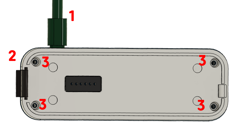
Um das Gerät mit Batterie nutzen zu können, muss das Batteriefach geöffnet werden:
- Gerät von der Stromversorgung trennen.
- Elektronikkapsel von der Sensorbasis trennen.
- Alle vier Schrauben lösen und die Haube von der Elektronikkapsel abnehmen.
Nach Einlegen von zwei AA-Batterien (1.5 V Alkaline) wird die Haube wieder aufgesetzt und mittels der vier Schrauben fixiert. In diesem Moment wird die rote LED blinken und damit einen Alarm anzeigen, da die Elektronikkapsel von der Sensorbasis entfernt wurde. Erst wenn die Elektronikkapsel wieder auf die Sensorbasis aufgesetzt wurde, wird der Alarm automatisch gelöscht.
Immer wenn eine externe Stromquelle vorhanden ist, wird diese unabhängig von den eingelegten Batterien verwendet. Die Batterien dienen dann als Backup bei Unterbrechung der Stromversorgung.
Im Batteriebetrieb sind die LEDs am Gerät deaktiviert – die Funktionalität ist ansonsten komplett identisch. Folgende Änderungen gelten im Batteriebetrieb:
- Im Normalbetrieb ist die LED ausgeschaltet.
- Im Alarmfall wird die LED und der Buzzer nur mit größerem zeitlichen Abstand kurz aktiv.
- Es werden keine einzelnen Wasserverbräuche gemeldet.
- Der Gesamtverbrauch wird nur noch jede Stunde übertragen.
- Die minimale Erkennungsschwelle für tropfende Wasserhähne ist leicht erhöht.
Alle anderen Funktionen des Gerätes wie Leckageerkennung, Tropfenerkennung etc. werden weiterhin ausgeführt.
Technische Daten
Teil 1
| Parameter | Wert |
|---|---|
| SKU | AQMWIE01 |
| EAN | 4251295783-444 |
| Stromversorgung | |
| Betriebsmodi | Alternativ oder parallel: Ext. Netzteil oder Batterie |
| Netzteil | 5V/2A USB-C |
| Batterie | 2 × AA, wechselbar |
| Kommunikation | |
| WLAN | IEEE 802.11b/g/n (2,4 GHz) |
| WLAN-Protokolle | Aqua-Scope Cloud, MQTT Client, JSON Webservice Client |
| LoRaWAN | EU868 (oder wie konfiguriert), Class A, LoRaWAN 1.0.3 |
| Bluetooth | 5 LE, UART Profile |
| Bedienung | |
| Tasten | Eine Taste |
| LEDs | 3-farbig (rot/grün/gelb) |
| Sensor-Technik | |
| Verfahren | Differenzielles Time-of-Flight (DTOF) |
| Messfrequenz | 1 MHz Ultraschall |
| Signalstärke | -7,5 ... 30 dB (kalibrierbar) |
| Unterstützte Rohre | |
| Durchmesser | 15–56 mm |
| Materialien | PEX, PEX AL, Weichkupfer, PP, PE |
| Ansprechschwellen | |
| Minimale Sensitivität | 1–3 l/min (einstellbar) |
| Tropferkennung | ab 0,1 l/min (kalibrierungsabhängig) |
| Rohrbrucherkennung | > 30 l/min (konfigurierbar) |
| Abmessungen/Gewicht | |
| Maße | 110 × 60 × 40 mm |
| Gewicht | 310 g (ohne Batterien) |
| Schutzgrad | IP44 |
| Lagerung/Transport | 0–40 °C, 10–90 % RH |
Teil 2 (entsprechend MID/OIML-R49)
| Parameter | Wert |
|---|---|
| Druck | PN10 (rohrabhängig) |
| Wassertemperatur | 0,1 °C ... 70 °C (T70) |
| Overload flow rate (Q4) | 3 125 l/h |
| Elektromagnetische Klasse | E1 (residential, commercial, light industrial) |
| Klimatische Klasse | 5 °C ... 30 °C in condensating/damp environment |
| Umweltklasse | B (MID), fixed installation with minimal vibrations |
Technische Unterstützung und Kontaktinformation
Sollten bei Ihnen Probleme mit diesem Produkt auftreten, dann geben Sie uns bitte die Gelegenheit, das Problem mit Ihnen gemeinsam zu lösen, bevor Sie das Produkt wieder an uns oder Ihren Händler zurücksenden.
- Telefon (deutschsprachig): +49 375 57214208
- eMail: info@aqua-scope.com
- Webseite: www.aqua-scope.com